Hardware Sync#
Note
You need one Analog Output (AO) card and one Digital Output (DO) card to run this tutorial.
Tip
We omit details to keep tutorials short. See API reference and docstrings for full descriptions.
from nistreamer import NIStreamer
In this tutorial, we will use 2 different cards simultaneously to generate both analog and digital signals:
ni_strmr = NIStreamer()

ao_card = ni_strmr.add_ao_card(max_name='Dev2', samp_rate=1e6)  # <-- replace `Dev2` to match your setup
do_card = ni_strmr.add_do_card(max_name='Dev3', samp_rate=10e6)  # <-- replace `Dev3` to match your setup

ao_chan = ao_card.add_chan(chan_idx=0)
do_chan = do_card.add_chan(port_idx=0, line_idx=0)
We will use the following minimal sequence to test start sync - both cards output a single pulse simultaneously at t=0:
ni_strmr.clear_edit_cache()

ao_chan.const(t=0, dur=10e-6, val=1)
do_chan.high(t=0, dur=10e-6)

ni_strmr.compile();
No sync (default)#
By default, cards are not synchronized, so start times may differ significantly:
ni_strmr.run(nreps=100)
Start trigger#
Now let’s enable start trigger sync. In our case, the two PCIe cards are connected by RTSI cable (other connections can be used, e.g. PFI terminals connected through a BNC cable, see discussion below).
We need the following settings:
ao_card.start_trig_out = 'RTSI0'
do_card.start_trig_in = 'RTSI0'
ni_strmr.starts_last = ao_card.max_name
Here:
ao_cardis configured to export start trigger pulse to line0ofRTSIbus;do_cardis set to await an external start trigger at itsRTSI0terminal;ao_cardis marked as the “starts last” - streamer will ensure that AO card starts only after DO card has started already and is armed to receive the trigger.
We can view full settings of each card and the streamer by printing them:
ao_card
AO card Dev2

Channels: ['ao0']

Hardware settings:
	Sample rate: 1,000,000.0 Sa/s

	Start trigger:
		 in: None
		out: RTSI0
	Sample clock:
		 in: None
		out: None
	10 MHz reference clock:
		 in: None
		out: see NIStreamer.ref_clk_provider setting

	Min buffer write timeout: 5.0 sec
do_card
DO card Dev3

Channels: ['port0/line0']

Hardware settings:
	Sample rate: 10,000,000.0 Sa/s

	Start trigger:
		 in: RTSI0
		out: None
	Sample clock:
		 in: None
		out: None
	10 MHz reference clock:
		 in: None
		out: see NIStreamer.ref_clk_provider setting

	Min buffer write timeout: 5.0 sec

	Const fns only: True
ni_strmr
NIStreamer instance

AO cards: ['Dev2']
DO cards: ['Dev3']

Hardware settings:
	Calc/write chunk size: 150.0 ms
	   10MHz ref provider: None
	     Starts-last card: Dev2
You should now see both pulses happening simultaneously (up to the finite AO signal rise time):
ni_strmr.run(nreps=100)

Setup file#
In the actual experiment, you will likely have multiple cards and many tens of channels in use. Registering all of them and specifying all sync configs every time would be quite tedious.
However, this setup typically doesn’t change often - once written, you would only modify it if some hardware connection changes. This is why it is convenient to write the whole streamer setup in a separate .py file and then simply import it in every script notebook. And after that you can maintain this file by updating it according to hardware changes.
This is how we can pack our tutorial setup into a single file (let’s name it streamer_setup.py):
from nistreamer import NIStreamer as _NIStreamer  # `_` prevents re-import with wildcard `import *`
ni_strmr = _NIStreamer()

ao_card = ni_strmr.add_ao_card(max_name='Dev2', samp_rate=1e6)
do_card = ni_strmr.add_do_card(max_name='Dev3', samp_rate=10e6)
# ... a few more cards registered here ...

ao_chan = ao_card.add_chan(chan_idx=0)
do_chan = do_card.add_chan(port_idx=0, line_idx=0)
# ... many more channels registered here ...

# Sync:
TRIG_LINE = 'RTSI0'
ao_card.start_trig_out = TRIG_LINE
do_card.start_trig_in = TRIG_LINE
# ... sync settings for other cards ...
ni_strmr.starts_last = ao_card.max_name
Now the full demo code reduces to:
from streamer_setup import *
ni_strmr.clear_edit_cache()

ao_chan.const(t=0, dur=10e-6, val=1)
do_chan.high(t=0, dur=10e-6)

ni_strmr.compile();
ni_strmr.run(nreps=100)
Other sync mechanisms#
Apart from start trigger, a few more hardware sync mechanisms are available:
Shared sample clock (set by
samp_clk_in/outproperty of cards);10 MHz phase reference for onboard clock PLL (set by the combination of
ref_clk_inproperty of cards andref_clk_providerproperty of the streamer; see docstrings for details).
Tip
You can refer to the "Device Routes" tab in NI MAX for each card to find available hardware signals and which terminals they can be routed to:

Choosing PFI vs RTSI/PXI_Trig#
Typically, NI cards have two connectors for sync signal input/output:
the front-panel connector (corresponding lines are called
PFI);the “back” connector - either
RTSIon PCIe cards, orPXI_Trigon PXIe cards.
Either can be used. However, when using the front-panel PFI, the sync pulses are travelling through the same cable with the generated output. This may lead to a noticeable crosstalk, especially significant for AO outputs.
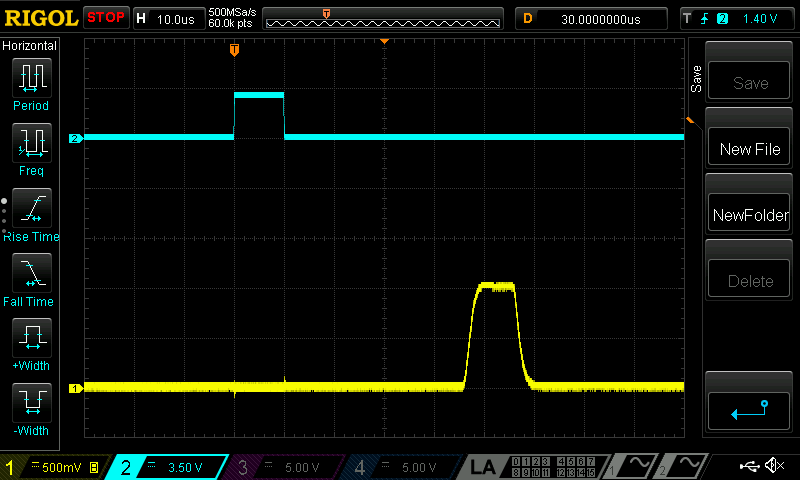
In the examples above, we were intentionally using the “back” RTSI connector. Let’s change the settings to use the front-panel PFI instead (you also need to connect the cables accordingly):
ao_card.start_trig_out = 'PFI0'
do_card.start_trig_in = 'PFI0'
ni_strmr.starts_last = ao_card.max_name
ni_strmr.run(nreps=100)

You can notice the main difference - the spike and ringing on the AO channel at zero time. It is induced by the start trigger pulse emitted by AO card and propagating through the same cable to the breakout box as the analog signal itself.
This is why it is recommended to route sync signals using the “back” connector, if possible.